MRI Lab general

MRI lab heads: Nadège Bault & Matt Roser

_images/Prisma_Pic.jpg

Starting a new study

Lab resources

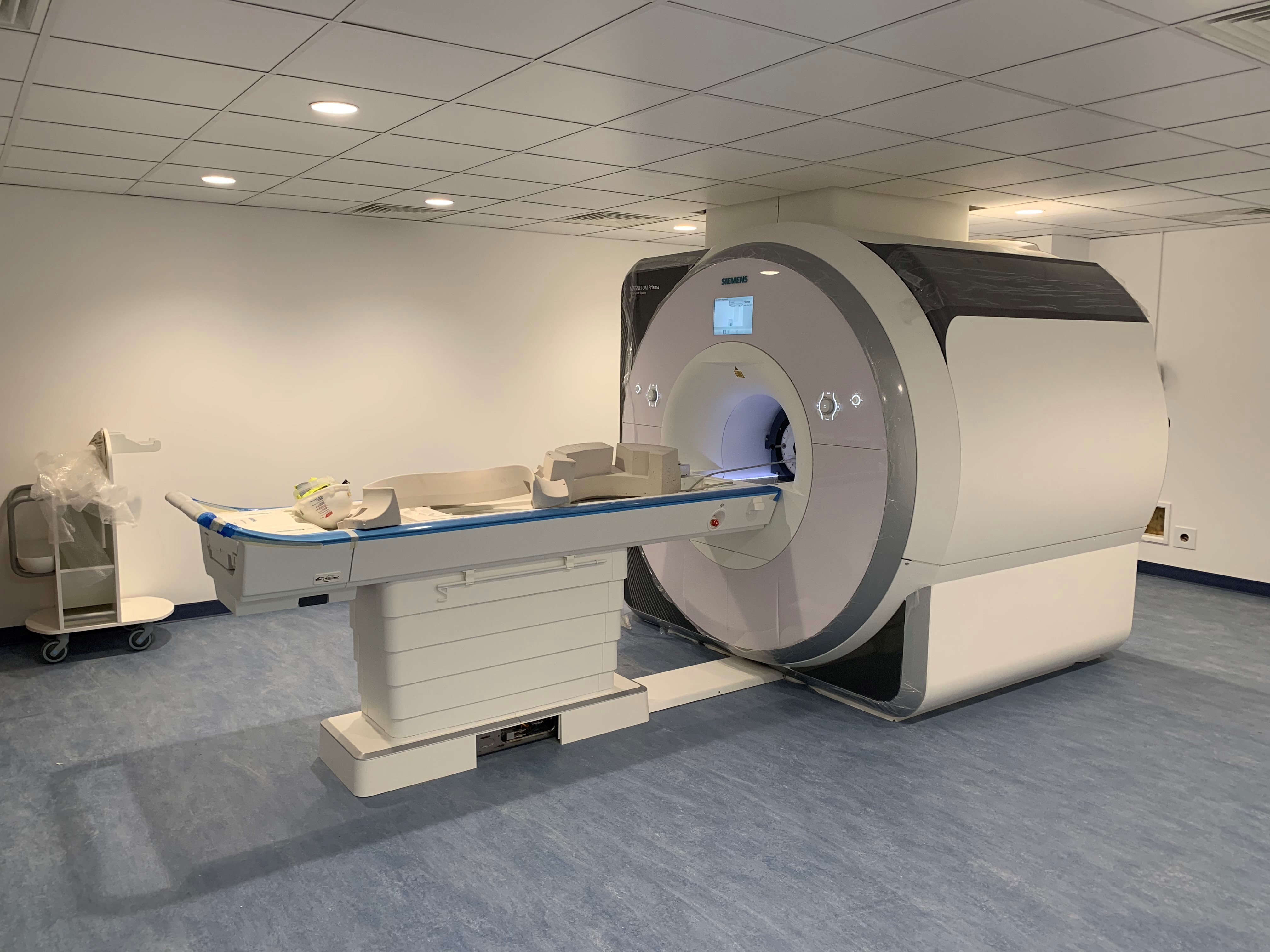
Information about our MRI scanner the Siemens Prisma 3T can be found here link

Submitting a project

Safety and ethics

See these documents for details of BRIC MR Safety and Operating rules and policies.

BRIC MRI Local Rules

BRIC Safety and Risk Operational Policy

Safety training

Before being able to access the MRI lab, you will need to complete a safety training. Safety training sessions may be ran monthly or bi-monthly, depending on the needs, in small groups. Please contact the lab heads (BRIC.MRI-lab.heads@plymouth.ac.uk).

Safety questionnaires must be filled by staff and research participants before they can enter the restricted MRI environment.

safety questionnaire - adult research participants

safety questionnaire - staff (permit to work)

General information for participants

This general information form contains information for patients/participants about the MRI environment, how to prepare for a session and how to come to BRIC. Please add your contact information at the end of the form before sending it to your participants!


Developing and testing a task

You should book a phantom pilot session before your start your data collection.

MRI Peripherals and Experimental Software

Overview

We have a range of peripherals that allow researchers to conduct psychological and cognitive neuroscience experiments in the MRI scanner.

Stimulus presentation

Cambridge Research BOLDScreen 32

This 1920x1080 @120 Hz screen is positioned at the top of the bore and can present visual stimuli which are viewable in the scanner using the mirror attachment.

The Getting Started guide is available here. BOLDScreen32_Getting_Started

Find more information on how to use the screen here: Screen instructions and notes.

Cambridge Research BOLDfonic Audio System

This system allows audio delivery, trigger control and synhronisation with the BOLDScreen. It includes two earphone/headphone options:

  • Ultra-thin piezo-electric headphones (HP PI US 03). These headphones work both inside and outside the MRI room.

  • Electrodynamic insert headphones (HP AT 01). These earphones only work within the scanner’s magnetic field.

HP PI US 03 piezo-electric headhpones

HP PI US 03 piezo-electric headphones

HP AT 01 electrodynamic earphones

HP AT 01 electrodynamic earphones

Find more information on how to use the audio system here: Sound presentation instructions and notes.

Response devices

We currently have two options to record participants’ manual responses in the scanner

  • a set of HHSC-2x4-C response buttons. One is labelled (on its back) for use in the right hand.

  • a HHSC-JOY-5 Tethyx Joystick

HHSC-2x4-C response buttons.

HHSC-2x4-C response buttons (left and right).

HHSC-JOY-5 Tethyx Joystick

HHSC-JOY-5 Tethyx Joystick

Find more information on how to set up the response devices below (Response device instructions and notes).

Experimental software

In the MRI control room is a Windows desktop computer running experimental software including:

The computer receives input from the response devices and scanner as keyboard (or mouse) events. You can use these to record responses and to record or sync to the scanner trigger.

Response device instructions and notes

Response devices input optical signals from the MRI room to the FIU-932Universal fORP Interface in the control room.

The fORP box receives button/joystick responses, as well as the optical trigger sent by the scanner at the start of each volume acquisition

The fORP box sends button presses and the scanner trigger as ascii characters to the presentation desktop computer. The ascii character corresponding to the scanner trigger is “t”.

More information on using the fORP932 is available here: Getting Started fORP932 and on this manufacturer website

Button box

For studies using the button boxes, the fORP box should be set as shown in the photo below. Check that the display is not flashing. This can happen if the experimental machine goes to sleep. Restart the box if flashing.

FIU-932Universal fORP Interface

FIU-932Universal fORP Interface

The two rows of LEDs on the fORP box show incoming responses using the buttons. The LED at the bottom of the rightmost pair shows the scanner trigger. The top is power.

The buttons output ascii characters via USB to the stimulus presentation computer. The table below shows the mapping of characters to buttons:

HHSC-2x4-C response buttons
Ascii characters output by button boxes

Button colour

blue

yellow

green

red

Right hand

b

y

g

r

Left hand

e

w

n

d

Finger

index

middle

ring

pinky

Joystick

For studies using the Joystick, the fORP box should be set according to these available options. Use the right wheel on the fORP box to scroll.

HD Joystick:

buttons act as mouse click.

Joystick Mouse:

works as a mouse with click.

HID Joy Comp:

non-responsive.

Screen instructions and notes

The Getting Started guide is available here. BOLDScreen32_Getting_Started

The following notes assume that you are presenting visual stimuli using the Windows desktop computer in the MRI control room.

Windows screen settings

By default, the screen in the MRI room should mirror the right-hand-side monitor in the control room, while the left-hand side monitor should not be seen by the participant in the scanner.

To achieve this, ensure the following screen settings are set on the Windows desktop computer:

  • right-click on the desktop and click “Display settings”

  • in “Rearrange your displays”, select display #1, #2 or 1|2

  • in “Multiple Displays” at the bottom of the Display settings page:

    • select “Duplicate desktop on 1 and 2

    • check “Make this my main display”

  • in “Rearrange your displays” at the top, select display #3

  • in “Multiple Displays” at the bottom of the Display settings page, select “Extend to this display”

Sound presentation instructions and notes

The full user guide for the MR Confon BOLDfonic sound presentation system is available here. BOLDfonic_MR Confon_User_Guide

Quick instructions for using the BOLDfonic audio system

These instructions assume that you are presenting sounds using the Windows desktop computer in the MRI control room.

  • Make sure that the MKII+ amplifier is turned ON (power button at the back)

  • Make sure that the MKII+ amplifier is using correct source: the right-side LCD shows “IN-STIM” as the source (corresponding to “fMRI” mode). If not, press the start button twice on the front side of the amplifier, or until “IN-STIM” shows.

Starter f MKII+ Amplifier

Starter f MKII+ Amplifier

  • Sound volume can be controlled at three levels:
    • the intensity level of your sound files. This should ideally be maximised beforehand so that your sounds use the largest amplitude range possible.

    • the output level of the sound card on the stimulus presentation computer. This can be set through the Windows OS (e.g. bottom right of the task bar).

    • the output level of the MKII+ amplifier, which can be set between -24 and +24 dB, relative to the input from the presentation computer, using the central dial.

  • Once you have chosen the sound level to use in your experiment, make a note of the sound levels on both the stimulus presentation computer and the MKII+ amplifier. Make sure you set the correct levels for each participant.

  • It is not possible to know the sound level of the presented stimuli in dB SPL unless the entire sound system has been calibrated. This is a complex process that requires additional equipment. Speak to the lab directors if this is something you need.

Desktop monitor speaker

Desktop monitor speaker

  • Sound presentation can be monitored in the control room using the desktop monitor speaker.

  • To control the monitor speaker’s volume:
    • Push the amplifier’s Volume dial once (the left LCD changes from “MUSIC-VOL” to “MUSIC-MONVL” on the first line and from “Balance” to “SUBJ-MONVL” on the second line).

    • SUBJ-MONVL is the Desktop Monitor speaker volume and can be adjusted using the Balance dial.

  • Sounds can be presented to the participants using either ultra-slim piezo-electric headphones or electrodynamic earphones

HP AT 01 electrodynamic earphones

HP AT 01 electrodynamic earphones

HP PI US 03 piezo-electric headhpones

HP PI US 03 piezo-electric headphones

  • Piezo-electric headphones work both inside and outside the MRI room. Electro-dynamic earphones need to be within the scanner’s magnetic field to function. The earphones drivers (white cubes) must be placed just outside the head coil.

  • For both headphones and earphones, the right-ear side is marked in red.

HP AT 01 earplug with ear defender

HP AT 01 earplug with ear defender


  • Both headphones and earphones provide some noise attenuation, but additional noise protection should be provided:

    • When using the headphones, the participant should wear earplugs within them.

    • The insert earphones should be worn within the provided ear defenders.


  • The BOLDfonic system also allows one-way communication from the console room to the participant using the MR Confon’s technologist microphone. When using the BOLDfonic system, this microphone replaces the Siemens technologist microphone. Communication from the participant to the console room always uses the Siemens system.

MR Confon Technologist microphone

MR Confon Technologist microphone


  • To talk to the participant, press the “Talk” button on the microphone’s base. This will override any audio stimulus being presented.

  • To set the microphone level:

    • press the “Talk” button on the microhpone

    • use the Volume dial on the MKII++ amplifier


Which earphones/headphones should I use?

You should consider the following when choosing between headphones and earphones:

  • Sound level: Because participant should wear earplugs within the headphones, this limits the effective intensity level at which auditory stimuli can be presented. Depending on the stimuli used, the maximum volume allowed by the stimulus presentation computer and amplifier may be insufficient for the stimuli to be audible or intelligible through the ear plugs. With the insert earphones, on the other hand, sound is delivered by a tube going through the ear plug, and therefore higher intensity levels can be reached at the participant’s ear.

  • Distortions: because they carry sounds through narrow tubes, the earphones are likely to introduce larger spectral distortions in the stimuli than the headphones.

  • Testing outside the scanner: unlike the earphones, the headphones can work outside the scanner room and are therefore easier to test or calibrate.