Response device instructions and notes
The FIU-932Universal fORP Interface in the control room receives:
the optical trigger sent by the scanner at the start of each functional volume acquisition (P4 port in schematic below)
optical signals from the response pads or joystick in the MRI room (P5 port)

FIU-932Universal fORP back panel
The fORP box sends these signals as ASCII characters via USB (P3 port) to the stimulus presentation computer. The ASCII character corresponding to the scanner trigger is “t” and the ASCII characters from the response pads or joystick depend on the configuration of the fORP. The character mapping for the configuration(s) appropriate to each device is given in the relevant sections below.
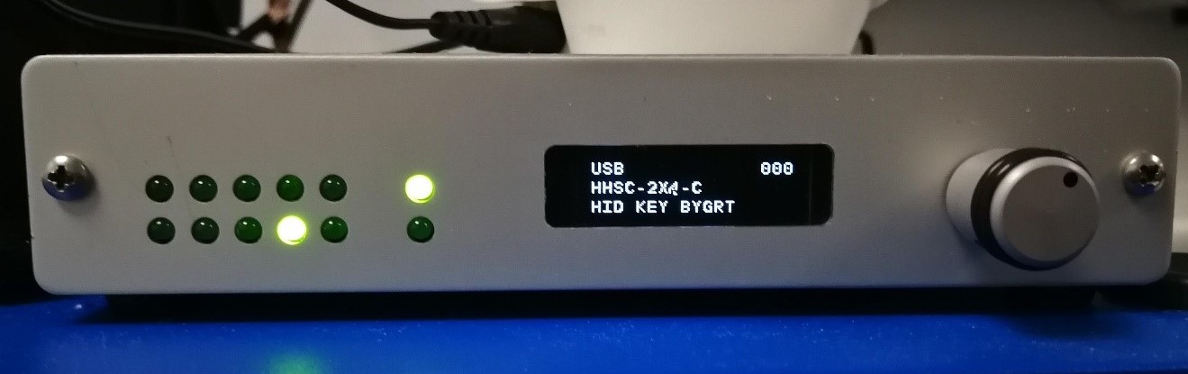
FIU-932Universal fORP Interface
The two rows of LEDs on the fORP box interface show incoming responses from the response device. The LED at the bottom of the rightmost pair shows the scanner trigger. The rightmost top LED is power. The central display indicates the current configuration
Check that the central display is not flashing. This can happen if the stimulation computer goes to sleep. Restart the box if flashing.
More information on using the fORP932 is available here:
Getting Started fORP932
and on this manufacturer website
Switching between response devices
When a new device is connected, the configuration of the fORP box does not automatically change to the appropriate configuration, even after restarting the box. The configuration must therefore be manually changed to the settings appropriate to the new device.
If a new device is to be connected, TURN OFF the fORP box at the power socket, then unplug and plug the old/new response device, then TURN ON the forp box. THEN Configure. (NOTE: Do not plug peripherals directly into the forp box. Plug them into the cable in the scanner room.)
To CONFIGURE: click the wheel button on the right side of the fORP interface, then turn the wheel to select YES for Changing Modes. This should then lead to Autoconfiguration. Displayed options depend on the currently connected device and are described in the relevant sections below.
2 x 4 Button boxes
For studies using the 2 x 4-button boxes, the fORP box should be set to USB, HHSC-2x4-C, HID KEY BYGRT (as shown in the photo above).
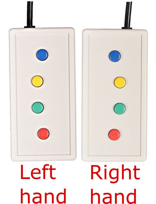
Button colour |
blue |
yellow |
green |
red |
Right hand |
b |
y |
g |
r |
Left hand |
e |
w |
n |
d |
Finger |
index |
middle |
ring |
pinky |
5-button Pyka ergonomic response pad
For studies using the 5-button ergonomic reponse pad, the fORP box should be set to: USB, PYKA, HID KEY BYGRT.
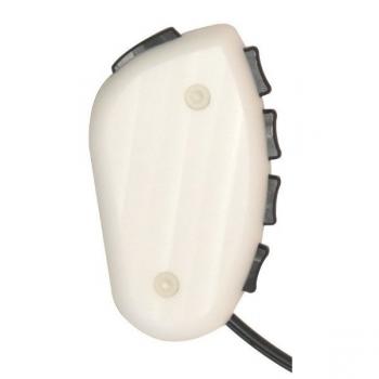
Finger |
thumb |
index |
middle |
ring |
pinky |
ASCII character |
b |
y |
g |
r |
m |
Note: if the configuration is incorrectly set to HHSC-2x4-C instead of PYKA (i.e. the configuration was not changed from that of the 2 x 4 response pads), the character for the little finger will be “e” instead of “m”.
Joystick
For studies using the joystick, the fORP box can be set to the following available options (use the right wheel on the fORP box to scroll to configuration):
- HD Joystick:
buttons act as mouse left click. No cursor location control.
- Joystick Mouse:
works as a two-button mouse with click. Front trigger is right click; top button is left click.
- HID Joy Comp:
non-responsive.
The Joystick can also be used as a two-button response device under configuration HHSC-2x4-C, HID KEY BYGRT. The front trigger is ‘b’ and the top button is ‘n’. No cursor control is available.