MRI Peripherals and Experimental Software
Overview
We have a range of peripherals that allow researchers to conduct psychological and cognitive neuroscience experiments in the MRI scanner.
Stimulus presentation
Cambridge Research BOLDScreen 32
This 1920x1080 @120 Hz screen is positioned at the top of the bore and can present visual stimuli which are viewable in the scanner using the mirror attachment.
The Getting Started guide is available here.
BOLDScreen32_Getting_Started
Find more information on how to use the screen here: Screen instructions and notes.
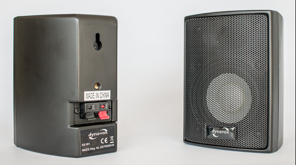
Cambridge Research BOLDfonic Audio System
This system allows audio delivery, trigger control and synhronisation with the BOLDScreen. It includes two earphone/headphone options:
Ultra-thin piezo-electric headphones (HP PI US 03). These headphones work both inside and outside the MRI room.
Electrodynamic insert headphones (HP AT 01). These earphones only work within the scanner’s magnetic field.
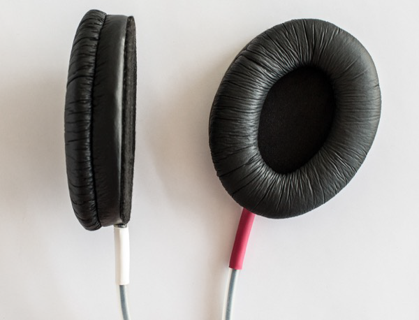
HP PI US 03 piezo-electric headphones
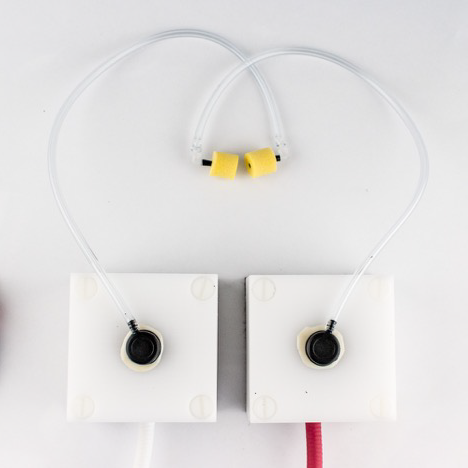
HP AT 01 electrodynamic earphones
Find more information on how to use the audio system here: Sound presentation instructions and notes.
Response devices
We currently have three options to record participants’ manual responses in the scanner
a set of HHSC-2x4-C response pads (4 buttons per pad, one pad per hand; right-hand pad labelled on its back).
a Pyka 5-button ergonomic response pad (single hand, left or right)
a HHSC-JOY-5 Tethyx Joystick
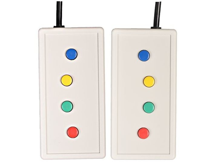
HHSC-2x4-C pads.
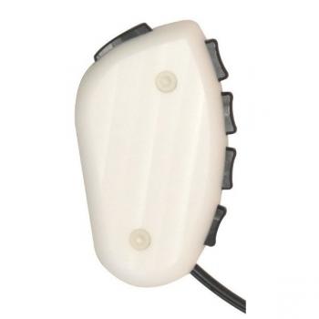
Pyka 5-button pad.
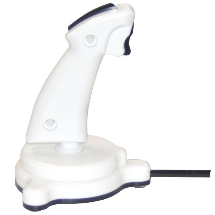
HHSC-JOY-5 joystick
Find more information on how to set up the response devices below (Response device instructions and notes).
Experimental software
In the MRI control room is a Windows desktop computer running experimental software including:
Matlab Psychtoolbox
OpenSesame (We do not recommend the use of OpenSesame for time-critical designs. OpenSesame is not suitable as the timing accuracy is too low.)
The computer receives input from the response devices and scanner as keyboard (or mouse) events. You can use these to record responses and to record or sync to the scanner trigger.
Detailed guides
Response device instructions and notes
The FIU-932Universal fORP Interface in the control room receives:
the optical trigger sent by the scanner at the start of each functional volume acquisition (P4 port in schematic below)
optical signals from the response pads or joystick in the MRI room (P5 port)

FIU-932Universal fORP back panel
The fORP box sends these signals as ASCII characters via USB (P3 port) to the stimulus presentation computer. The ASCII character corresponding to the scanner trigger is “t” and the ASCII characters from the response pads or joystick depend on the configuration of the fORP. The character mapping for the configuration(s) appropriate to each device is given in the relevant sections below.
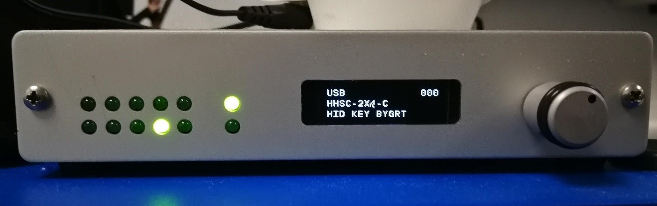
FIU-932Universal fORP Interface
The two rows of LEDs on the fORP box interface show incoming responses from the response device. The LED at the bottom of the rightmost pair shows the scanner trigger. The rightmost top LED is power. The central display indicates the current configuration
Check that the central display is not flashing. This can happen if the stimulation computer goes to sleep. Restart the box if flashing.
More information on using the fORP932 is available here:
Getting Started fORP932
and on this manufacturer website
Switching between response devices
When a new device is connected, the configuration of the fORP box does not automatically change to the appropriate configuration, even after restarting the box. The configuration must therefore be manually changed to the settings appropriate to the new device.
If a new device is to be connected, TURN OFF the fORP box at the power socket, then unplug and plug the old/new response device, then TURN ON the forp box. THEN Configure. (NOTE: Do not plug peripherals directly into the forp box. Plug them into the cable in the scanner room.)
To CONFIGURE: click the wheel button on the right side of the fORP interface, then turn the wheel to select YES for Changing Modes. This should then lead to Autoconfiguration. Displayed options depend on the currently connected device and are described in the relevant sections below.
2 x 4 Button boxes
For studies using the 2 x 4-button boxes, the fORP box should be set to USB, HHSC-2x4-C, HID KEY BYGRT (as shown in the photo above).
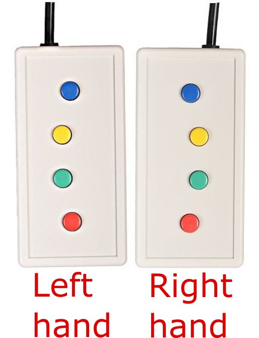
Button colour |
blue |
yellow |
green |
red |
Right hand |
b |
y |
g |
r |
Left hand |
e |
w |
n |
d |
Finger |
index |
middle |
ring |
pinky |
5-button Pyka ergonomic response pad
For studies using the 5-button ergonomic reponse pad, the fORP box should be set to: USB, PYKA, HID KEY BYGRT.
Finger |
thumb |
index |
middle |
ring |
pinky |
ASCII character |
b |
y |
g |
r |
m |
Note: if the configuration is incorrectly set to HHSC-2x4-C instead of PYKA (i.e. the configuration was not changed from that of the 2 x 4 response pads), the character for the little finger will be “e” instead of “m”.
Joystick
For studies using the joystick, the fORP box can be set to the following available options (use the right wheel on the fORP box to scroll to configuration):
- HD Joystick:
buttons act as mouse left click. No cursor location control.
- Joystick Mouse:
works as a two-button mouse with click. Front trigger is right click; top button is left click.
- HID Joy Comp:
non-responsive.
The Joystick can also be used as a two-button response device under configuration HHSC-2x4-C, HID KEY BYGRT. The front trigger is ‘b’ and the top button is ‘n’. No cursor control is available.
Screen instructions and notes
The Getting Started guide is available here.
BOLDScreen32_Getting_Started
More detailed specifications are available here (Technical Data tab)
Windows screen settings
This section assumes that you are presenting visual stimuli using the Windows desktop computer in the MRI control room.
By default, the screen in the MRI room should mirror the left-hand-side monitor in the control room, while the right-hand side monitor should not be seen by the participant in the scanner.
To achieve this, ensure the following screen settings are set on the Windows desktop computer:
right-click on the desktop and click “Display settings”
in “Rearrange your displays”, select display #1, #2 or 1|2
in “Multiple Displays” at the bottom of the Display settings page:
select “Duplicate desktop on 1 and 2
check “Make this my main display”
in “Rearrange your displays” at the top, select display #3
in “Multiple Displays” at the bottom of the Display settings page, select “Extend to this display”
Viewing distance and angular size of visual stimuli
This section is useful if you need to calculate the angular size of stimuli presented on the screen. The angular size of a stimulus depends on the viewing distance (the distance between the participant’s eyes and the screen).
Screen distance from participant’s eyes
The viewing distance from the participant’s eyes can be estimated as the sum of the following distances:
Distance between screen and rear end of the magnet bore:
When the screen cart is placed on the floor markings, the screen is located 43 cm away from the rear end of the bore.
When the screen card is placed against the bore, this distance is reduced to 2 cm
Distance between isocentre and rear end of the bore: 107.5 cm
Horizontal distance between mirror and isocentre:
Radiographers usually place the participant in such a way that their eyebrows approximately line up with the isocentre.
The distance between the eyes and the eyebrows is approximately 2 cm
Therefore, the horizontal distance between the isocenter and the mirror (at the location where the participant fixates) is also 2 cm
Vertical distance between the participant’s eyes and the center of the mirror: approximately 16 cm
The total viewing distance is therefore 43+107.5+2+10 = 168.5 cm at the floor markings or 127.5 cm when the screen is placed against the bore.
Angular size of stimuli
Given the above distances, 1 cm on the screen approximately subtends:
0.34 degrees of visual angle at the floor markings [\(2 \times \arctan(1/168.5/2) / \pi \times 180 = 0.34\)]
0.45 degrees of visual angle against the bore [\(2 \times \arctan(1/127.5/2) / \pi \times 180 = 0.45\)]
At the default resolution of the screen (1920 x 1080), and given the screen dimensions (69.84 x 39.29 cm), the conversion factor between stimulus size in pixels and stimulus size in degrees of visual angle is (approx.):
80.85 pixels/degree at the floor markings [\(1920 / 69.84 / \arctan(1/168.5/2) / 2 \times \pi / 180 = 80.85\)]
61.18 pixels/degree against the bore [\(1920 / 69.84 / \arctan(1/127.5/2) / 2 \times \pi / 180 = 61.18\)]
Maximum eccentricity of the display
Assuming that the screen is centred on the bore and that the participant fixates the centre of the screen, the maximimum eccentricity in the visual field at which stimuli can be presented on the screen depends on the viewing distance:
When the screen is placed at the floor markings (43 cm away from the rear end of the bore):
The full width of the screen (69.84 cm) approximately fills the entire bore aperture as seen by the participant from the isocentre. So, the maximum eccentricity along the horizontal meridian of the visual field (at either side of the screen) is 11.83 degrees [\(2 \times \arctan(69.84/2/168.5/2)/\pi*180 = 11.83\)]
The full height of the screen is visible, so the maximum eccentricity along the vertical meridian of the visual field is (top or bottom of the screen) is 6.67 degrees [\(2 \times \arctan(39.29/2/168.5/2)/\pi*180 = 6.67\)]
When the sceen is placed against the bore:
Only about 59 cm of the screen width is visible to the participant (the diameter of the bore is 58 cm along most of its length, with a slight widening to 67 cm near the end). So, the maximum eccentricity along the horizontal meridian of the visual field (at either side of the screen) is 13.20 degrees [\(2 \times \arctan(59/2/127.5/2)/\pi*180 = 13.20\)]
The full height of the screen is visible, so the maximum eccentricity along the vertical meridian of the visual field is (top or bottom of the screen) is 8.81 degrees [\(2 \times \arctan(39.29/2/127.5/2)/\pi*180 = 8.81\)]
When against the bore, additional markings on the floor near the rear end of the bore allow you to horizontally centre the screen with the bore.
Sound presentation instructions and notes
The full user guide for the MR Confon BOLDfonic sound presentation system is available here.
BOLDfonic_MR Confon_User_Guide
Quick instructions for using the BOLDfonic audio system
These instructions assume that you are presenting sounds using the Windows desktop computer in the MRI control room.
Make sure that the MKII+ amplifier is turned ON (power button at the back)
Make sure that the MKII+ amplifier is using correct source: the right-side LCD shows “IN-STIM” as the source (corresponding to “fMRI” mode). If not, press the start button twice on the front side of the amplifier, or until “IN-STIM” shows.
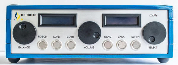
Starter f MKII+ Amplifier
- Sound volume can be controlled at three levels:
the intensity level of your sound files. This should ideally be maximised beforehand so that your sounds use the largest amplitude range possible.
the output level of the sound card on the stimulus presentation computer. This can be set through the Windows OS (e.g. bottom right of the task bar).
the output level of the MKII+ amplifier, which can be set between -24 and +24 dB, relative to the input from the presentation computer, using the central dial.
Once you have chosen the sound level to use in your experiment, make a note of the sound levels on both the stimulus presentation computer and the MKII+ amplifier. Make sure you set the correct levels for each participant.
It is not possible to know the sound level of the presented stimuli in dB SPL unless the entire sound system has been calibrated. This is a complex process that requires additional equipment. Speak to the lab directors if this is something you need.
Desktop monitor speaker
Sound presentation can be monitored in the control room using the desktop monitor speaker.
- To control the monitor speaker’s volume:
Push the amplifier’s Volume dial once (the left LCD changes from “MUSIC-VOL” to “MUSIC-MONVL” on the first line and from “Balance” to “SUBJ-MONVL” on the second line).
SUBJ-MONVL is the Desktop Monitor speaker volume and can be adjusted using the Balance dial.
Sounds can be presented to the participants using either ultra-slim piezo-electric headphones or electrodynamic earphones
HP AT 01 electrodynamic earphones
HP PI US 03 piezo-electric headphones
Piezo-electric headphones work both inside and outside the MRI room. Electro-dynamic earphones need to be within the scanner’s magnetic field to function. The earphones drivers (white cubes) must be placed just outside the head coil.
For both headphones and earphones, the right-ear side is marked in red.
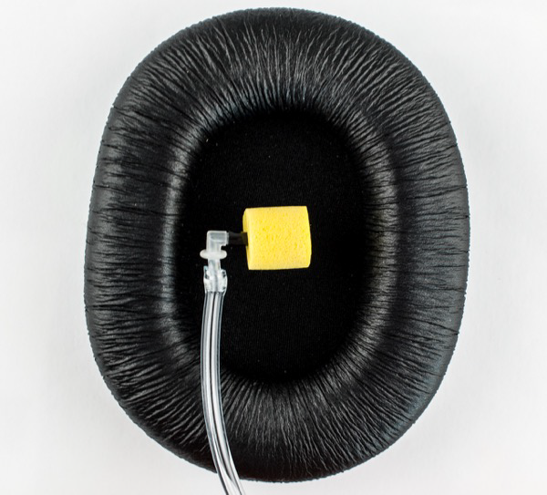
HP AT 01 earplug with ear defender
Both headphones and earphones provide some noise attenuation, but additional noise protection should be provided:
When using the headphones, the participant should wear earplugs within them.
The insert earphones should be worn within the provided ear defenders.
The BOLDfonic system also allows one-way communication from the console room to the participant using the MR Confon’s technologist microphone. When using the BOLDfonic system, this microphone replaces the Siemens technologist microphone. Communication from the participant to the console room always uses the Siemens system.
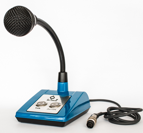
MR Confon Technologist microphone
To talk to the participant, press the “Talk” button on the microphone’s base. This will override any audio stimulus being presented.
To set the microphone level:
press the “Talk” button on the microhpone
use the Volume dial on the MKII++ amplifier
Which earphones/headphones should I use?
You should consider the following when choosing between headphones and earphones:
Sound level: Because participant should wear earplugs within the headphones, this limits the effective intensity level at which auditory stimuli can be presented. Depending on the stimuli used, the maximum volume allowed by the stimulus presentation computer and amplifier may be insufficient for the stimuli to be audible or intelligible through the ear plugs. With the insert earphones, on the other hand, sound is delivered by a tube going through the ear plug, and therefore higher intensity levels can be reached at the participant’s ear.
Distortions: because they carry sounds through narrow tubes, the earphones are likely to introduce larger spectral distortions in the stimuli than the headphones.
Testing outside the scanner: unlike the earphones, the headphones can work outside the scanner room and are therefore easier to test or calibrate.